Last updated at Fri, 15 Dec 2023 00:26:52 GMT
Many security professionals and researchers are intrigued by the idea of opening up and exploring embedded technologies but aren’t sure where to start. In this blog post, we will point you toward a good starting point by covering a number of tools, basic methods, and concepts.
Tools
Often, the first question people have when breaking into hardware hacking is, “Which tools do I need?” For the most part, only some basic tools are necessary to get started.
Tools commonly used by those conducting testing and research on embedded technology fall into the following categories:
- Disassembly and assembly
- Electronic signal analysis and measurement
- System control and injection
These tools can come in many forms and cost anywhere from $20 to $30 each to upward of hundreds of dollars. In this guide, we’ll start with some basic tools in each category, but you can build out your tool sets further as you grow in experience and need.
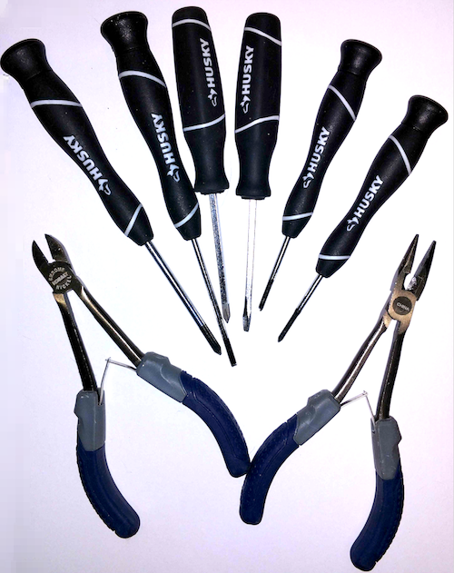
Disassembly and assembly
A good set of screwdrivers and pliers are very important here.
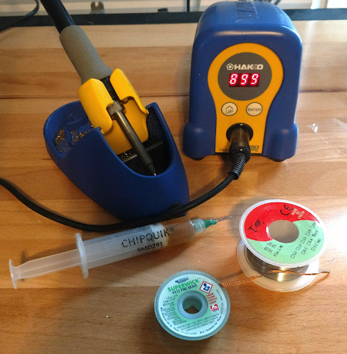
Also, it’s typical to need to be able to solder and de-solder. Here, I would recommend spending a few extra dollars and buy an adjustable temperature soldering iron with interchangeable tips. You will need solder, solder flux, and de-solder wick.
Electronic signal analysis and measurement
In this category, I recommend two must-have tools: a simple digital multimeter and a logic analyzer.
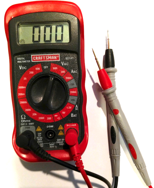
A digital multimeter will come in hand for measuring voltage levels on devices and components, identifying ground, and mapping out circuit paths on circuit boards.
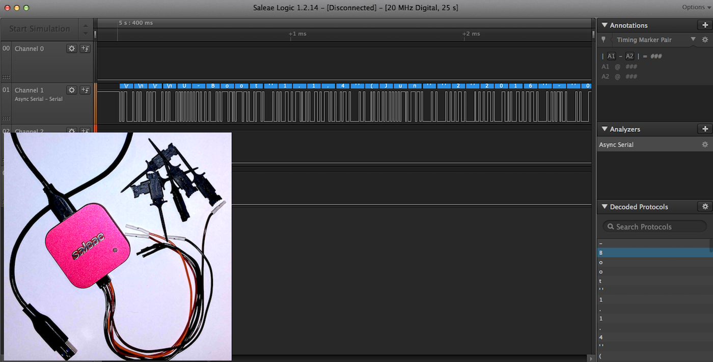
Logic analyzers are one of the primary analysis tools used by hardware researchers, testers, and engineers for analyzing digital signals on embedded devices. There are several brands out there, but I would recommend the Saleae, mainly because it’s a quality-built device and has several models available for different budgets.
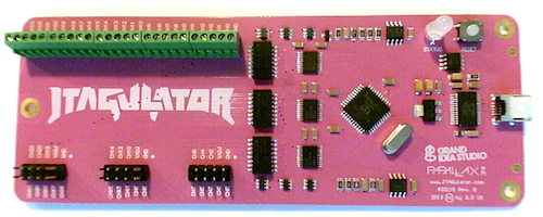
Another tool that can come in handy for identifying JTAG and UART ports is the JTAGULATOR. This tool allows you to connect all the pins of a header and automatically walk through and test all the possible pinout combinations to identify JTAG or UART.
System control and injection
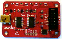
This final group of tools helps with gaining access to, extracting, and/or altering data on the embedded technology. In this category, there are several inexpensive options available. The first is the faithful Bus Pirate, which gives you the ability to connect to the UART, I2C, SPI, and JTAG communication protocols.
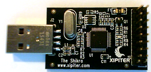
The Shikra is a similar device that supports UART, JTAG, and SPI protocol access, and is much faster than the Bus Pirate when extracting flash memory over SPI.
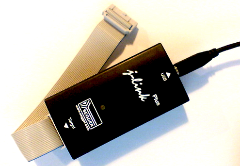
The Seggar J-link is another tool for testing JTAG and Serial Wire Debug (SWD) and is more robust than Bus Pirate or Shikra. This JTAG tool is available in both a professional version and in a less-expensive education version.
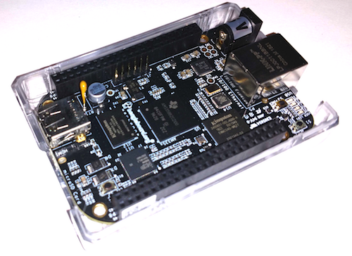
Also, for a good, all-around test tool, don’t forget about the BeagleBone Black. This development platform can be used to conduct a number of tests.
To finish up, some basic odds and ends are needed, including jumper wires and headers that let you connect to the embedded devices for testing and hacking. Check out the following short list:
- 1.27mm male straight single-row pin header
- 2.54mm male straight single-row pin header
- Male-to-male solderless flexible breadboard jumper wires
- Male-to-female solderless flexible breadboard jumper wires

Hardware disassembly
The first phase of hardware hacking often involves gaining some physical access into the device. Here, you need to move slowly and be cautious to avoid damaging the equipment of injuring yourself.
A quick examination of the bottom of the device will often reveal screws used to disassemble the device. Sometimes these assembly screws can be hiding under labels and rubber feet, so don’t forget to check that out.
Another method is to look for FCC records. To do this, you first need to determine whether the device uses any wireless or radio frequency (RF) communication. If it does, it should have an FCC ID. This is often labeled on the device as a requirement by the FCC.
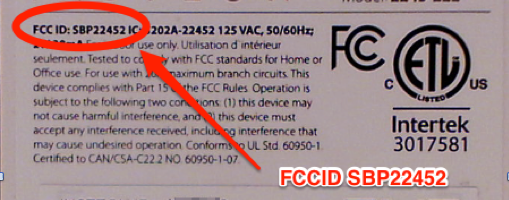
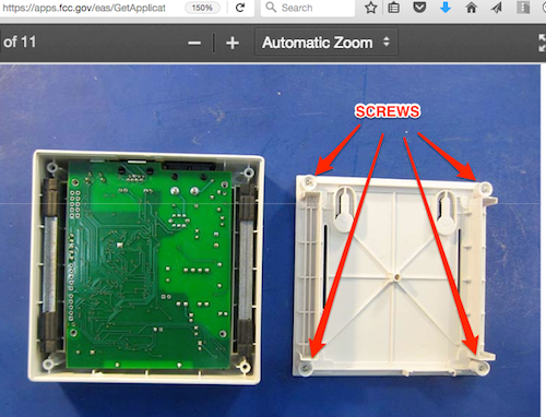
The FCC ID can be entered in at this website, which will return items such as RF test reports as well as internal and external images of the hardware. The internal images are the most helpful, as they’ll often reveal how the device is assembled.
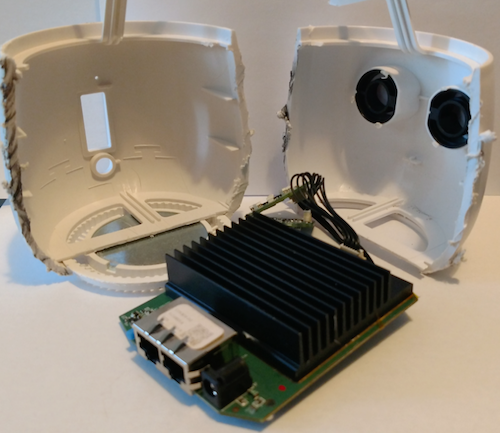
If you find out the case is glued or epoxied shut, all bets are off and you may need to use a Dremel tool or other potentially destructive tools to cut it yourself. If so, follow all safety precautions to ensure you don’t damage the circuit boards or worse, injure yourself. An example of this method is shown below:
Circuit examination
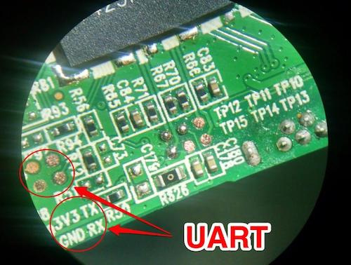
Once inside the device, the goal is to identify and map out the circuit and components. A quick visual examination may reveal that the manufacturer has marked the board for key debugging connections such as JTAG, UART, and SWD:
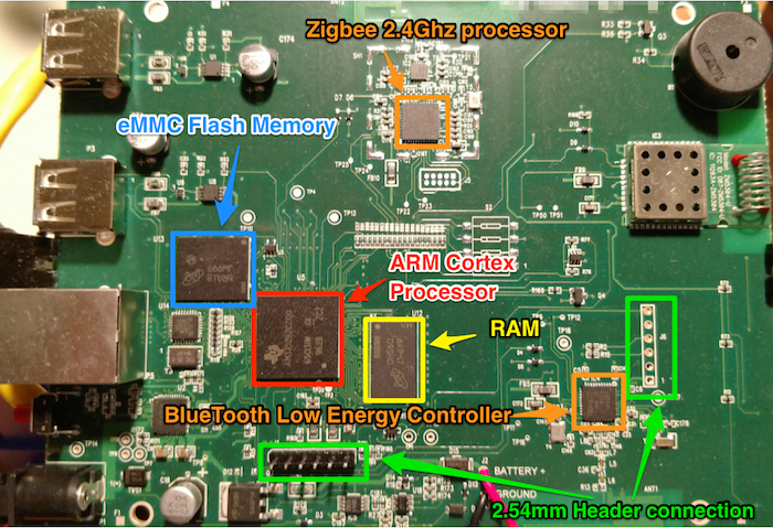
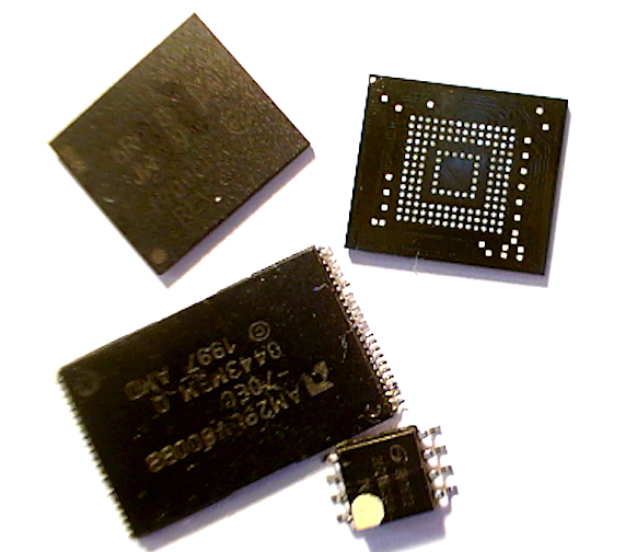
After examining the board for obviously marked debug ports, I like to focus on identifying other important features such as header connections, which may be used for JTAG, UART, or other forms of debug access. Also, at this point, you will want to identify all the key IC chips (CPU, memory, RF, and WiFi).
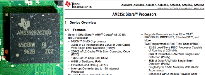
Once all the key IC chips have been identified, I recommend trying to download each of the identified component’s datasheets. These datasheets will play a significant role in further testing and analysis of the embedded device’s functionality and security. Most datasheets can be located by simply googling the device name and using the identifiers stamped on the face of the chips:
Firmware
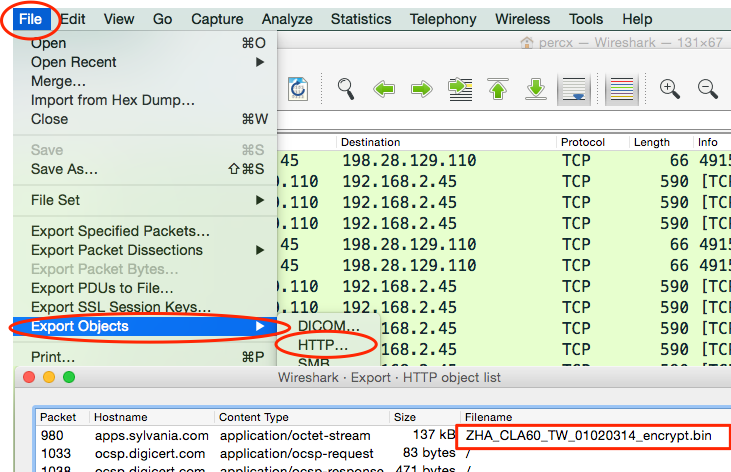
Examining firmware can also help reveal invaluable information when testing for security issues. There are a number of methods for gaining access to firmware. The first way is to see whether the vendor allows direct download over the internet. If firmware is not available directly from the vendor, my next step is attempting to capture it using Wireshark. This is accomplished by capturing all network communication while the embedded device is doing a firmware upgrade. If not encrypted, the firmware can often be extracted from the captured pcap data using the Export Objects feature within Wireshark.
If this is not possible, you may need to get more creative. Another option is via the examination of mobile application code used to manage or control the embedded device. It is not uncommon to see devices that are controlled and managed through your mobile phone also control the firmware upgrade process. With that in mind, examining the mobile application may reveal the URL Path and access codes needed to download the latest firmware.
Finally, when all else fails, it may be necessary to go directly to the flash memory storage on the device. There are multiple methods that are directly related to the type of flash memory on the board. This will require some research and analysis to identify the most effective method. For instance, can you read the flash in-circuit, or do you need it out of circuit, requiring you to de-solder the chip? Is it readable via SPI, or do you need some type of chip reader?
Spending some time doing research online and looking at the datasheets will help you properly identify the memory storage and best methods for data extraction. I always try to seek out others who have encountered the same memory extraction issues. In those cases, Google can be your friend for finding them and their documented methods.