Last updated at Wed, 07 Apr 2021 18:24:44 GMT
This blog is the sixth post in our annual 12 Days of HaXmas series.
As the story goes, you never learn to be a hacker—it’s just something you’re born as.
Just like most hackers, I couldn’t wait to take my Christmas toys apart to see how they worked when I was a child. And, of course, I was always able to put them back together in working order, so I was a natural-born hacker. My oldest brother took things apart, too, but once he did, he was rarely able to reassemble them, let alone make them work again. He, of course, went on to be a manager.
Jumping forward more than 40 years, and these skills have come into full play in my role as the Research Lead (IoT) here at Rapid7. One of the fun parts about my job is that I often get to take IoT technology apart. I use these opportunities to expand my knowledge on technology, electronics, and security for the purpose improving the knowledge of others, such as coworkers, customers, consumers, and manufacturers. So, I figured this year I would share my adventures on basic disassembly and examination on this year’s Christmas present.
Disassembling an Amazon microwave
Amazon recently released a basic, voice-controlled microwave oven. I couldn’t pass up looking at one of these devices, so I placed a pre-order and the device showed up at my house on Nov. 12 (Santa came a little early this year). My main goal was just to understand the construction of such devices. Since they all work around the frequency of 2.4 Mhz, how do you add WiFi and Bluetooth low-energy (BLE) communication to a microwave without having issues with interference from the microwave itself?
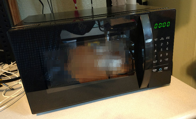
Once the microwave was unpacked, I powered it up and configured it to make sure it worked properly and I understood its general features. At first, the microwave starts up a BLE service. Using the correct mobile application, you attach to the BLE service and configure the WiFI access point (AP) connection settings. After that, the device reconnects via your WiFi AP and shuts down the BLE service.
At this point, it was time to tear down the device to identify and understand its components. First, always unplug a device for safety reasons—I learned that trick as a child, when I received a few serious electrical shocks poking around inside energized gear. But as they say, what doesn’t kill you makes you stronger.
When disassembling the device, the hardest part is often taking off the case, and that was no different here. All but one screw came out easily, but the last screw was torqued on so tight I had to use a Vise-Grip and a hammer to tap it loose. After a few minutes, I successfully removed the last screw and had the cover off.
Here, all caution should be taken to not move, change, or damage any of the oven shielding components. At that point, I was only interested in examining the electronics. In this case, there was only one circuit board, so I first documented all of the plugs and wiring connectors, then carefully removed the board from the chassis for examination.
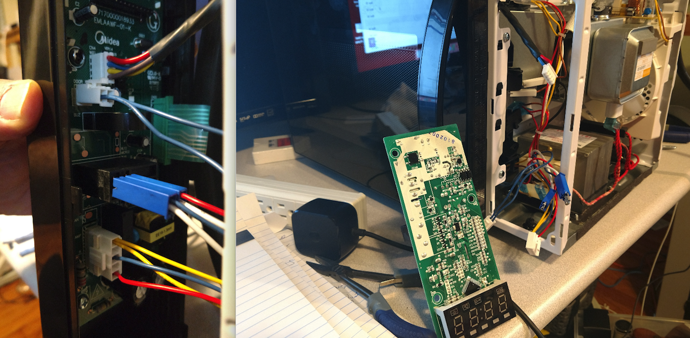
After physically examining it, I quickly realized there was no WiFi or BLE circuitry on the main circuit board and no more circuit board inside the microwave. However, while examining the main board, I did find a connector marked “WiFi.”
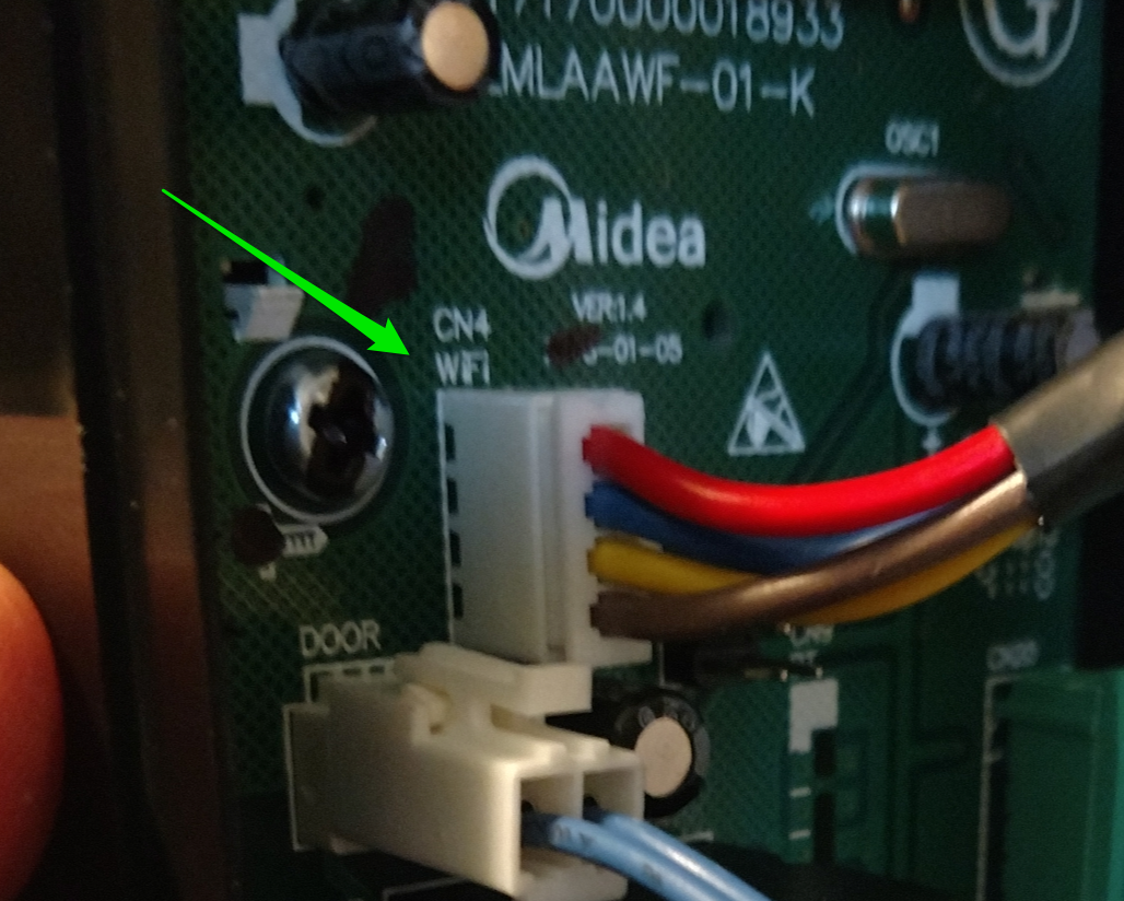
Tracing this connection back, I discovered that these four wires—which were also marked as universal asynchronous receiver transmitter (UART)—fed into the power cable. As I looked at the power cable, I saw the cable was marked as “WiFi Cable.” At first I was confused, but quickly realized that the best way to avoid issues with microwave communication interference was to move the WiFi and BLE further away from the oven and use a shielded cable to communicate to it. So, I assumed they placed the component in the head of the power plug. With a little work using a razor saw, I was able to confirm this.
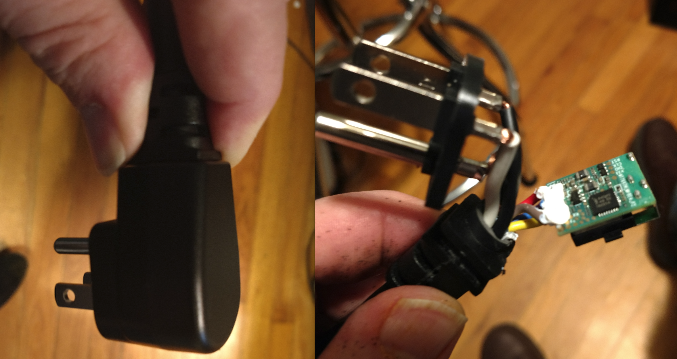
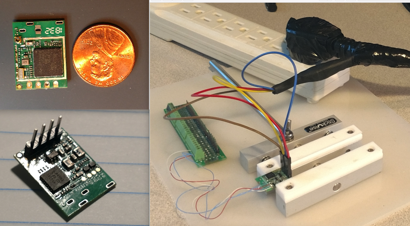
So, my next step was to remove the board, clean it up, remove any covers to gain access to the chips, and configure the power cable and connection so further testing could be done later. I first cleaned up the circuit board and added 2.54mm headers to it. Next, I extracted the four color-coded wires further up the shielded cable so I could add plug connectors to them. This allowed me to safely test the communication board with the microwave powered up.
In conclusion, we successfully disassembled a device and learned its basic construction and how it was designed to protect the communication from the microwave energy. We then safely reassembled the device so it still worked—and staged it so we could conduct further testing and analysis of the electronics at a future date.