Last updated at Tue, 19 Dec 2023 21:47:40 GMT
This is part two of a three-part series. Part one covered how to build a development workbench. Part two of this series will cover reading electrical diagrams and serve as a primer for part three, where we will re-engineer common circuit types found in vehicles.
Electrical Diagrams & Re-identification
Technically, your bench is complete at this point, and you can connect an OBD-II to USB conversion device to start interpreting the CAN Bus. But where's the fun in that? Let's dig a little further into process. Even if you don't expand your bench, knowing how to read wiring diagrams is crucial when troubleshooting electrical problems in your own vehicle.
First, no two sets of wiring diagrams are identical. Individual companies have an internal standard, but there isn't an accepted industry standard for labeling diagrams. I found that Haynes and Chilton vehicle manuals are fantastic for maintenance, but are terrible for wiring diagrams. There is a reason for this negative review: Both Haynes and Chilton group vehicles by revisions of the vehicle's' design. For example, the workbench I built for this guide was a 2006 Dodge Stratus with a 2.7L engine, and the appropriate book that coincides with this vehicle is: Chrysler Sebring, Dodge Stratus & Avenger 1995 thru 2006 (Haynes Repair Manual). The problem I ran into was that the wiring generally changes every couple of years, sometimes yearly.
Wilson's diagrams allow you to select an exact year, make, and model, although there are other diagrams available. I found that Wilson's diagrams were accurate for the vehicle I was using. If you have access to applications for mechanics, or you are willing to pay for a license, those programs are incredibly thorough and list any parts that you may need from your local auto shop.
There is only one sure fire way to learn about diagrams, and that's hands-on. Let's examine a wiring diagram for the driver's seat belt indicator:
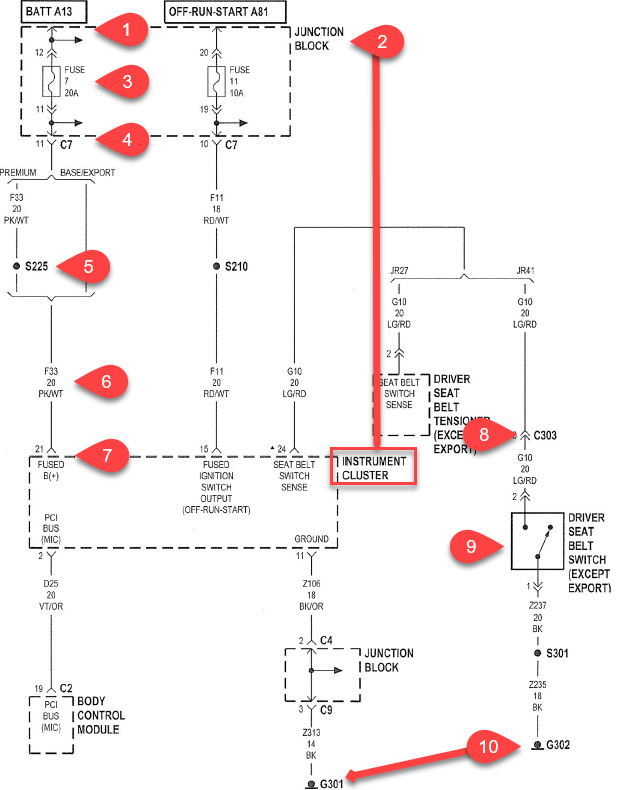
1. Power source. BATT A13 indicates that this is the thirteenth power source fed from either the battery or alternator, and is fed into fuse 7 on the junction block.
2. Equipment. The fuse in this vehicle is located within the junction block, but many vehicles have multiple junction blocks. So, check your diagrams and maintenance manuals for the exact name of the junction block. For example, the Wilson's diagrams refer to the junction block as the fuse panel attached to the BCM, while the fuse panel in the PDC is simply referred to as ‘PDC' to reduce confusion.
3. Fuse. Fuse 7 is a 20Amp fuse that transfers energy from the A13 circuit to connector C7 on pin 11.
4. Initial path of power. There is a lot happening here in the diagram. To continue the circuit, a pink and white (PK/WT), 20-gauge wire (See Item 6), transfers energy from connector C7's 11th pin, and the circuit is no longer A13, but rather F33. On a premium (luxury) vehicle, the pink and white wire follows a different path.
5. The S225 junction. This is a spliced wire. This is very common for initial power and ground wires.
6. Wire nomenclature. Read as fused circuit 33. 20-gauge wire. Pink and white in color.
7. Connection point. The energy of the circuit flows into the instrument cluster on pin 21.
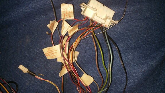
8. The C303 junction. This is a coupling connector. Your maintenance manual may or may not inform you of the exact location of couplings. To determine what exact number of the coupling is, scour your diagrams for other indications of the coupling number. Identifying groups of wires can help identify the exact coupling. Example, C303 in my vehicle is the only coupling to have the following combination:
a. C303, pin 12, white and blue
b. C303, pin 13, green and red
c. C303, pin 4, black
I recommend using a marker to write the number on the sides of the couplings as you identify them.
9. Switch. Albeit labeled as a switch, I specifically highlighted this section for you to understand that these are the type of circuits for which we can replicate either by installing a switch of our own or directly grounding the wire.
10. The G301 and G302 junctions. These are grounding points. It is likely that the grounding points will also not be identified by maintenance manuals. As a recommendation, tie all the grounding points wire all the grounding points in your bench to one physical connection. All electrical circuits need a ground to be complete. Grounding all the points together will ensure that any redesigned components you add or manipulate in the future will be grounded accordingly and leave you free to focus on the interaction of the circuit.
If you have never seen wiring diagrams or traced an electrical path in a vehicle, this can be daunting. The wiring diagram pages can have many different components smashed into one page, the wires likely will change colors, and possibly run through multiple adapters. Let's further examine the diagram to understand how power flows through a simple switch process: the driver's seat belt.
After learning to read the diagram, we will discover how easy it is to manipulate the circuit itself. In the figure below, the green line highlights the path of the circuit:

1. The circuit for the driver's seat belt indicator starts on a light green and small red striped, 20-gauged wire originating from pin 24 of the instrument cluster and is designated as ‘grounded circuit 10.'
2. From the instrument cluster, the initial light green and red wire terminates at coupling 303 male end on pin 13. The corresponding female coupling continues the circuit as a light green and red wire to the switch located in the driver's seat belt clip.
3. As the driver clicks the seatbelt, the circuit is grounded. Grounding completes the circuit (the next section of this guide will cover how to replicate this type of circuit as well as variable resistors).
4. The flow is now changed to a black, 18-gauge wire and connected to grounding point 302, which was probably connected to the body of the vehicle.
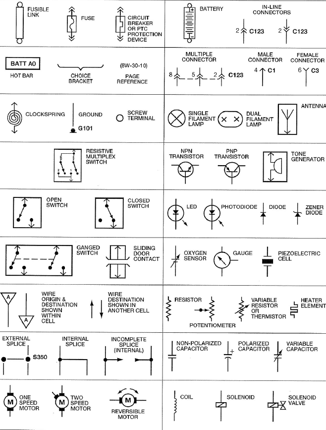
A good set of wiring diagrams should include a symbol identification chart, as seen here:
(Wilson Auto Electric, 2017)
References
Wilson Auto Electric. (2017, March 1). Wireing Diagrams. Retrieved from Wilson's TSB Database.