Last updated at Tue, 25 Apr 2023 20:43:57 GMT
Introduction
There is a vast body of knowledge hiding inside your car. Whether you are an auto enthusiast, developer, hobbyist, security researcher, or just curious about vehicles, building a development bench can be an exciting project to facilitate understanding and experimentation without risking possible damage to your vehicle. This is a perfect project for people of a wide range of ages and skill levels. Even if you have never worked on a car before, or you do not feel like your Electronics-Fu skills are strong, there are dozens of blogs, training videos, and reference guides on the internet that can supplement the information in this guide.
This the first part of a three-part series. Part one covers how to build the physical bench. Part two will discuss how to read wiring diagrams and serve as the primer to part three, where we will re-engineer common circuitry.
A car hacking workbench consists of the critical electronics that control the vehicle, plus bits and pieces of the electrical harness. This is like a neurosurgeon operating on a heart, brain, and spinal cord outside of the human body, except more accessible to the squeamish. Within this guide, we will explore:
- Finding a suitable vehicle
- Extracting the critical components
- Building and powering a workbench
- Re-engineering circuits and sensors
- Experimenting with your bench
You can adapt the following steps to any vehicle. We chose a 2006 Dodge Stratus, 2.7L, four-door sedan. This vehicle has a Controller Area Network (CAN) Bus interface accessible through the On-board Diagnostics (OBD-II) port. By reassembling the electrical components, we can connect to the vehicle's “brain” through the OBD-II port, and experiment with traffic on the CAN Bus.
Note: Some vehicle manufacturers do not share standards between production lines, or even between builds of the same make or model that are a year apart. Find information, such as wiring diagrams and parts, that are specific to your vehicle. For example, If you are working with a heavier class of vehicle, it may interface with the CAN Bus through a J1939 diagnostics port instead of an OBD-II connector. You may also find that newer hybrid vehicles have different power voltages that you need to be aware of while constructing your bench.
Tools
This project is going to take more than just a simple screwdriver and a pair of clippers. This is not a complete list, but here are some tools that you may want to have on hand:
- Phillips and flathead screwdrivers in assorted sizes
- Loppers and/or wire cutters
- Basic set of standard and metric socket wrenches, plus extension bits
- Wire strippers
- Safety equipment (gloves, goggles, light-weight face mask)
- Voltmeter (a cheap basic model is fine)
- Multimeter
- Flashlight
Important Note: When working in an old and dirty car or environment (such as a vehicle in a junkyard), WEAR A DUST MASK! Removing an electrical harness can expose you to heavy amounts of dust and bacteria. When the electrical harness is out of the car, wipe down all the components and cables with a small amount of a mild soap and water to reduce the risk of illness.
Time Requirements
Anyone with a moderate amount of mechanical or electrical knowledge could complete this project over a weekend (16-20 hours). Those with more limited knowledge of these two key areas may need two weekends: One to remove the physical components and a second to reassemble and test.
Part Requirements
No two vehicles are identical; however, all vehicles possess some commonalities. Your build may not require every component mentioned in this guide, but you should be at least familiar with the following terms:
- Power Distribution Center (PDC) – Channels power from the battery into the rest of the vehicle.
- Junction Box (also known as a fuse panel) – Fuses protect the wiring system. If a component faults and causes a power surge, the fuse will sacrifice itself to protect the wires in your vehicle from melting and causing severe damage.
- Powertrain Control Module (PCM) – Controls input and output to over a hundred various sensors placed on the engine and throughout the vehicle, then injects data into the CAN Bus, the vehicle information network. Generally, the PCM is a combination of the Engine Control Unit (ECU) and Transmission Control Unit (TCU). This is important to know, as wiring diagrams can introduce confusion by using PCM, ECU, and TCU interchangeably.
- Instrument Cluster (IC) – Located in the dash, this device is monitored by the driver and contains indicator levels, speedometer, RPM gauge, etc.
- Immobilizer (sometimes referred to as the skim module) – Connected to the ignition switch in the steering column, the immobilizer authorizes the key in use while starting the car. If the immobilizer is missing, unpowered, or the wrong key is in use, then the car will not start.
- Body Control Module (BCM) – Controls the functions associated with various circuits of the vehicle's accessories and communicates via the CAN Bus. May share a housing with in junction box.
- Ignition Switch & Key – The keys, tumbler, and power feed that start the vehicle.
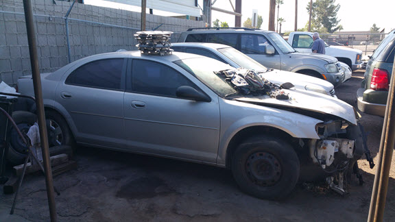
In order to source a vehicle to use for this project, we recommend that you call junkyards in your area and ask if they have any wrecked vehicles that still have all their components, electrical harness, and keys. Yes, it is that simple.
Pro Tip: make friends with the working professionals at the junk yards. I am not saying have them over for dinner or invite them to your weekly poker game, but explain your project and what you are looking for. Vehicles regularly come into junkyards following an accident. So, let the junkyard know what you're looking for in a vehicle. If they don't have what you're looking for, they may call you when something arrives.
As for the type of vehicle that you are looking for… that is completely up to you. If you just want a workbench to train on, then any vehicle newer than 2005 will do. Just remember that larger-class vehicles, such as class 3 or 6 , may use a J1939 connector instead of an OBD-II.
Step 2 – Removing the Electrical Harness
First, and most important: DO NOT CUT ANYTHING! At least not yet, anyway. Before you grab the clippers and go to town hacking into wires, I suggest taking the time to identify and label components, connectors, couplings, wires, and sensors. This will save an incredible amount of time in the long run. If you skip this step now, when everything is out of the vehicle and you're building your workbench later, you get to play a not-so-fun game called, “Where Does This Go?” (You may notice there aren't any pictures supporting this process) I played the game, and it's not fun. I can positively recommend: label everything before you begin! Even if you don't know what every piece under the hood is, marking items with a simple A, B, C pattern now can significantly reduce confusion in the future.
Second, take detailed pictures of connectors while they are still connected. If you choose to forego pictures, don't worry. Most connectors are designed to fit in only one socket and in only one direction. Also, for the ease of maintenance, engineers use couplings to attach wiring extensions from sensors and components to the main electrical harness.

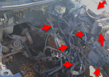
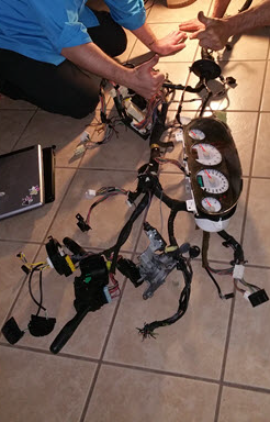
After completing the labeling and identification process, start to remove the components and wiring harness. There are two practical ways of removing everything that you need.
The first way is to simply unbolt and disconnect everything from the front of the engine compartment and unbolt anything in your path until you reach the steering wheel, then remove everything in one long piece. There is a tiny hiccup in this course of action: getting the cables out in one piece may require passing everything through a hole in the vehicle's firewall, which may be smaller than some of the major components. To make this process simpler, disconnect any unit that will not fit before passing the cables through the hole, pull the cables just far enough, and reconnect the unit when the last connector is through the other side. This way you won't forget how something was connected in the first place.
The second way is to cut the entire system into two large pieces: one consisting of everything under the hood and a second made up of everything within the vehicle. This method makes it easy to remove all pieces from the vehicle, but will require that you reconnect two pieces with electrical caps or other types of connectors.
Now, grab your safety gear and tools, roll up your sleeves, and get to it. Just a heads up, do not wear something that you will want to wear ever again. This can be an extremely dirty job. Mike Rowe would be proud. Furthermore, if you cherish your health, even just the tiniest bit, wear a dust mask.
Step 3 – Initial Testing
Now that everything is out of the car, make sure that it can receive power. If you cut the harness into pieces, you will need to reattach the cut wires. Reconnect the harness to the instrument cluster, PDC, PCM, BCM, and ignition systems. At this point, you can just lay everything out across a large flat surface.
Powering your harness is different from normal power management in a vehicle. Some components can be directly powered from the battery and others wait until the car is running. Plus, when the car is running, everything is powered from the alternator, which is an AC circuit. Instead we will need to use power from an outlet, which is a DC circuit. Luckily, we are not powering an entire car, so we can replicate the battery's DC connection through the Power Distribution Center (PDC).
Car batteries generally hold approximately 12.6 volts (or slightly higher) when the vehicle is not running, and will shoot up between 13.7V to 14.7V when running (except for hybrid or electric vehicles, which are completely different ball games, and too much detail for this section). If you have a variable power station, you are good to go, but portability and expense can become an issue. During this project, I used a generic variable DC power adapter cranked up to 12V at 1.2 amps and did not experience any trouble powering the harness and components. You may have to strip the ends of the adapter and either solder the wires (safe option) or like me, clamp down partially stripped wires with alligator clips (not recommended, but okay for initial testing only). Screw terminals are also a safe option, and perhaps the most versatile power management utility if you are unsure how you want your bench to look at the moment.
To complete the power connection, find the positive terminal on the PDC, usually indicated with a red plus symbol. Inside the PDC there should be a metal bar that transfers current to the various fuses and relay circuits, and in turn to the rest of the vehicle. Connect the negative (grounding) wire of the adapter to a vehicle ground. If you are unsure if the circuit is complete, check for continuity with a voltmeter by connecting one probe on positive and the other on cables (which we recommended that you label earlier) to ground. Keep changing the probe from one ground point to another until the voltmeter shows continuity and/or holds a tone indicating the completed circuit. Finally, plug in the 12V DC power adapter to the power source (i.e., a wall outlet).
Provided the ignition system was hooked up, power is available, the immobilizer is connected, and the keys are in the ignition switch, when you turn the key, the instrument panel should light up. Just about every sensor available through the instrumentation cluster will indicate there's a problem. Take a deep breath, it's normal: obviously, a missing car engine will cause warnings!
If you didn't get power, check connectors, couplings, and fuses first. If power still isn't going through the system, grab your handy-dandy multimeter and check all available grounding wires. If you have never used a multimeter to check volts, resistance, amps, or continuity, then I suggest watching this video from Ratchet and Wrenches.
Switch your multimeter into continuity mode and touch each prong to the positive and grounding (negative) wires of your adapter. If you do not hear a beep, the circuit is incomplete. Move the negative prong of the multimeter around to various grounding points until you hear a beep. Now move your grounding (negative) wire from your power source to that new location. This should correct the problem.
Important Note: When power is available, and the instrument cluster is active, disconnect the DC power adapter from the power source, THEN the PDC and grounding point. Failure to do so could create a spark, shock you, or possibly start a fire in a worst-case scenario.
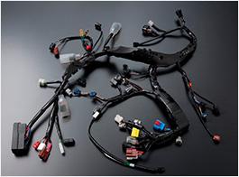
Step 4 – Unwrap & Thin Out the Electrical Harness
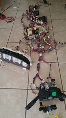
Now that you have power to the main components, start removing the black electrical tape and fire barrier from all wires in the harness. I recommend wearing gloves, as the stickiness of the tape can tear into your hands after a while. You may be tempted to cut into the tape surrounding the wires, which is fine, but make sure that you do not cut any of the wires during the process.
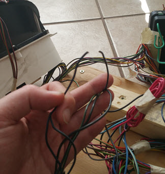
After stripping the tape from the wires, spread the electrical harness and connected components as far apart as possible. Examine the harness for any connectors that are not plugged into any equipment. These connectors are not needed to complete the bench, and can be removed. While clipping connectors, leave a 6-8” pigtail. You do not want to clip the wires at the base of the connectors; depending on how you develop your workbench beyond this guide, you may need one of those connectors in the future.
Now that unnecessary connectors are gone, remove excess wires that are not connected to anything. This will help thin out the harness and keep the cable management process clean.
Step 5 – Design & Build Your Workbench
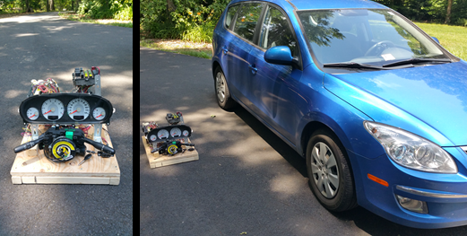
This step in the process is COMPLETELY YOUR OWN! That said, you may have space requirements. While I was building my workbench, I wanted it to be portable and not too bulky, so I could ship it across the country for peers to learn from and practice on. Pictures available online through web searches show that some people have the system stretched out on a lab table, a large board, or even the garage floor. Others have used Lego and Erector sets to build vertical mounting racks. My entire bench had to fit inside a large travel case, so there were height, width, and length requirements. No matter how you choose to build your workbench, leave enough physical space between components that both hands can easily work inside without a struggle.
Design, build, and then re-power the unit. If the instrument cluster lights up after turning the key to the start position on the ignition switch, you are good to go.
Ready for part two? Read it here.